


The Chandra X-ray Observatory is one of NASA’s Great Observatories, together with the Hubble Space Telescope, the Spitzer Space Telescope and the now deorbited Compton Gamma Ray Observatory. The Chandra Observatory, launched in 1999 and still operational, carries a telescope with an angular resolution of half an arcsecond, two imaging cameras and two different types of transmission gratings with dedicated read-out detectors.
The imaging capability of the telescope allows mapping of extended sources such as nearby supernova remnants and distant clusters of galaxies. The grating spectrometers provide detailed spectra (60-1000 over 0.4-10 keV; 40-2000 over 0.09-3 keV) from many different classes of objects, ranging from coronae of nearby stars to active galactic nuclei in the distant Universe.
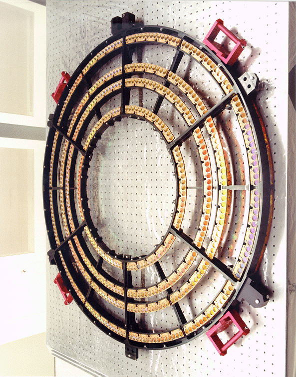
SRON and the Max Planck Institut für Extraterrestrische Physik (MPE) have provided the Low Energy Transmission Grating (LETG). The actual gratings were manufactured and tested by MPE, and SRON produced the ring-like structure in which the gratings are placed. SRON is the Principal Investigator institution for the LETG, ultimately responsible for the entire low energy grating experiment.
Chandra has been put in an elliptical earth orbit by the Space Shuttle in July 1999 and has been operating successfully up until now.
Science
The Chandra mission’s core scientific objective is the study of astrophysical plasmas in point-like sources. Prime candidates for study are stellar coronae, white dwarf atmospheres, X-ray binaries, cataclysmic variables and active galactic nuclei. Measurements of plasma emission lines allow the determination of physical parameters such as gas temperature and density, ionization state, elemental abundances, velocities and redshifts.
Technology
The spectral coverage of Chandra ranges from 0.09 to 10 keV. The Low Energy Transmission Grating addresses the longer wavelengths in this range, up to about 140 Ångström (0.09 keV).
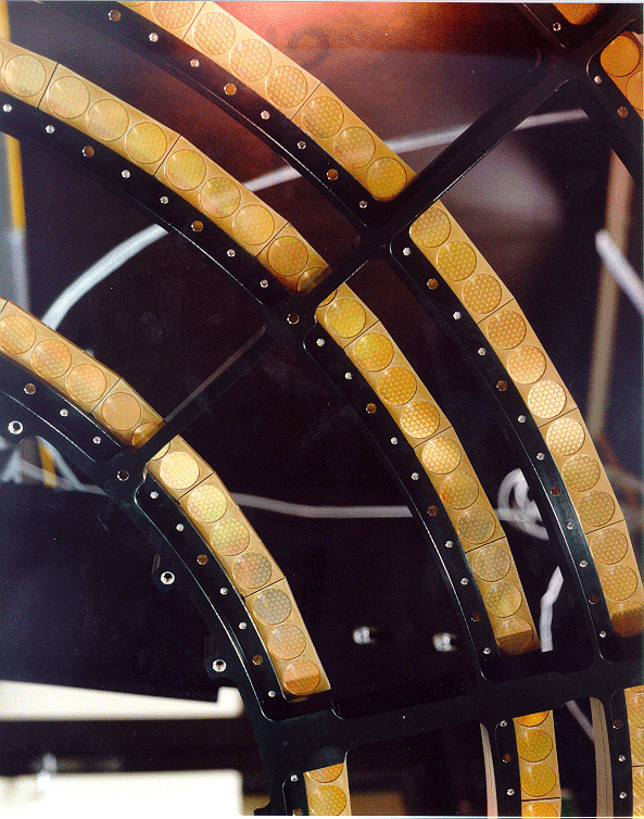
The grating is placed behind Chandra’s mirrors and intercepts the converging bundle there. The grating consists of no less than 540 elements, made by the Max Planck Institute MPE. Each element has a gossamer-thin structure of a thousand parallel independent gold threads per millimeter. The grating elements are located in rings with a diameter of 1.5 centimeters. Two supportive structures support the thin threads: a linear grating with a distance of 25.4 micrometers between the wires and a triangular pattern of wires with a distance of 2 millimeters between the wires. SRON produced the ring-shaped structure in which all of the grating elements are located. As the Principal Investigator, SRON is also responsible for the entire grating.
With the grating, a spectral resolution of 1000 is possible. This means that the energy of the photons captured can be measured to an accuracy of 0.1%. The grating has an average efficiency of 10%, with a peak of 20% for radiation of 2 keV.
The grating diffracts the radiation into differentcolors, creating an X-ray rainbow on the focal plane at a distance of almost 10 meters. There, the detectors that observe the X-rays are located. The user of the satellite can opt for CCDs (Charge Coupled Devices) or MCPs (Multi Channel Plates), dependent on the wavelength that they want to observe. The lower noise CCDs are only sensitive to radiation up to 60 Ångströmwhereas the MCPs can measure across the entire wavelength range.
The working principle behind a grating is based on the wavelength characteristic of electromagnetic radiation. A grating bends radiation at specific angles if it satisfies the requirement that the difference in wavelength between two adjacent slits constitutes exactly one or more wavelengths. The wavelength can be derived for the angle at which the radiation is bent and the distance between the wires of the grating. In Chandra, the grating elements are located in the convergent bundle. The shape of the structure in which the elements are located has been chosen such that the ‘light’ of each wavelength is focused at a separate point.
Links
- Chandra @Harvard
- Chandra/CXC @Harvard
- Chandra/LETG @MPE
- Chandra/LETG @NASA
- Chandra Observatory on Twitter and Facebook